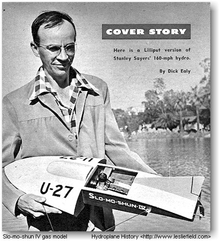
Build Slo-mo-shun IV
[1952] |
|
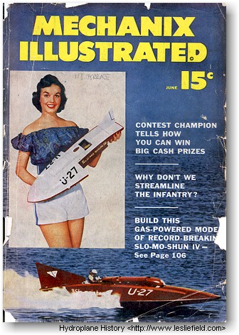
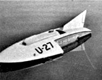
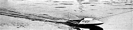
A new world's one-mile record for unlimited hydroplanes was set by Slo-Mo-Shun IV on June 26, 1950, at Seattle, Wash. Driven by its owner, Stanley Sayers [sic], this Allison-powered craft flashed across the water at an incredible 160.323 mph. The previous record of 141.74 mph had been set way back in 1939 in England by Sir Malcolm Campbell's Blue Bird II [sic].
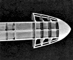
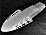
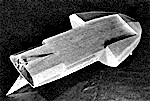
In hull form, Slo-Mo-Shun IV closely resembles the familiar three-step hydroplane. It is different, however, in one important respect-it has a small V-bottom section at the bow. At speed, a conventional three-step hydro rides on just the two side sponsons and the extreme stern.
 |
 |
 |
| Top view of the boat after framing fn the two sponsons. | Bottom view at same stage of completion as shown at left. | Bottom of the completed boat. Note that rudder is offset. |
 |
 |
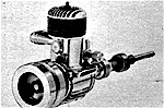 |
| Port side showing the control bridle and the bridle mounts. | Starboard side. A fishline is employed for a control line. | Power is furnished by an 0&R .29 glow-plug marine engine. |
 |
||
|
Our model planes like its prototype and is strong and stable enough to take a .65-cu.in. engine. |
||
If the speed goes high enough, air flowing into the tunnel formed by the sponsons creates enough lift to make the boat become semi-airborne. This results in a dangerous loss of directional stability. To overcome this, Slo-Mo-Shun IV has the afore-mentioned V-bottom section at the bow. It's called a "spoiler" and serves to break up or "spoil" the unwanted stream of air.
One other unusual feature of the boat deserves mention. Instead of the usual center-line rudder, Slo-Mo-Shun IV has one that's offset to starboard. This was found to be the best position after a lot of experimentation. A center-line rudder, being directly in the slipstream of the propeller, took an unholy beating. Twin rudders were unsatisfactory because, due to the torque of the propeller, the port one did little work. The single offset rudder has been completely reliable. The air rudder in the tail section is an experimental feature and is locked in place so it cannot be used when racing in sanctioned contests.
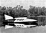
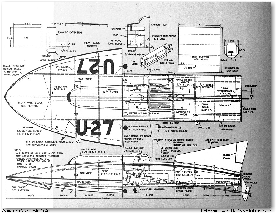
Slo-Mo-Shun IV is presented here in scale-model form. The scale is 1 in. equals 1 ft. The model planes like the real thing when powered by an Ohlsson & Rice .29 glow-plug marine engine. All drive accessories — universal, stuffing box, shaft, strut, and shear pin — are also O&R products. A 1½x1½-in. prop is used. If more power and higher speed are desired, the hull is strong enough and stable enough to permit using an engine with a displacement as high as .65 cu. in.
Before starting to build the model, read every word of this article and study the accompanying drawings. This procedure will ease your task immeasurably.
 |
| For screen quality image click on the thumbnail above. For higher resolution TIFF image suitable for printing on a laser printer click here. |
 |
| For screen quality image click on the thumbnail above. For higher resolution TIFF image suitable for printing on a laser printer click here. |
|
BILL OF MATERIALS (Approximate Quantities Required) Mahogany Aircraft Plywood 3 pieces, .070" x 12" x 30". (if unobtainable locally, this plywood can be purchased from General Veneer, P.O. Box 271, Southgate. Calif.) Balsa Gussets: I piece, 1/16" x 2" x
18" Pine Hull Top Braces: I piece, 3/16" x ¾"
x 36" Maple Engine Beds: 2 pieces, ¾" x 7½" x 7?" Fastenings 4 brass ½" No. 6 flathead wood screws Miscellaneous Bridle Mounts: 1 piece, extruded dural angle, ?" x
¾" x 12½" I piece, Japanese tissue, 24" x 30" |
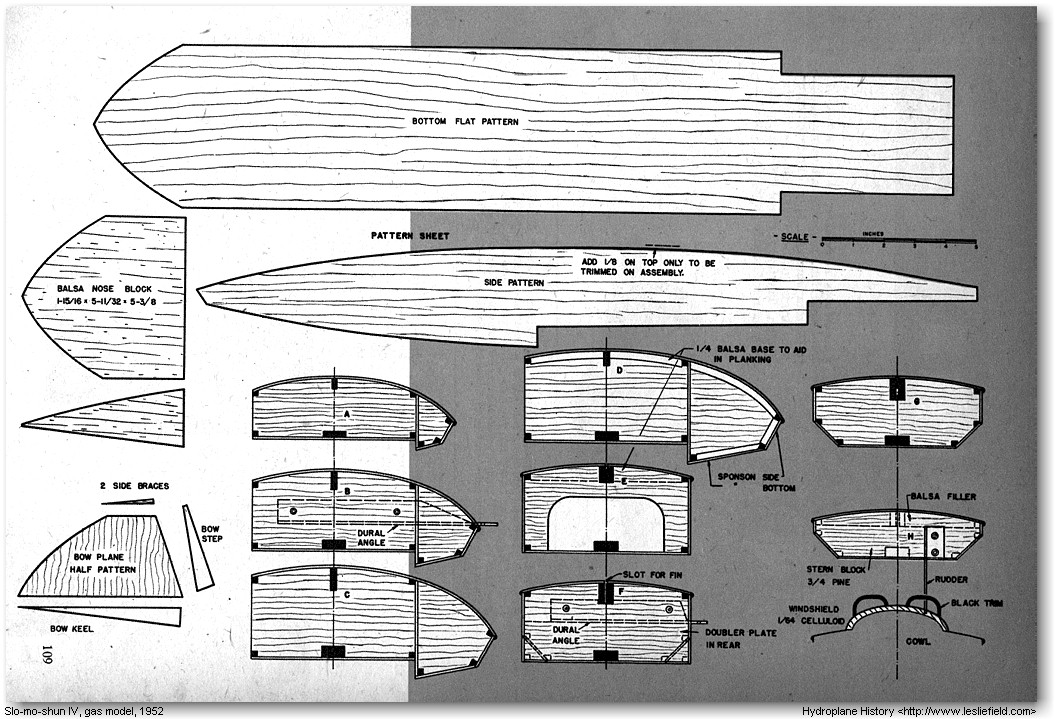
Make the keel from 5/16x¾-in. pine. Splice as shown between Bulkheads A and C. Plane off the lower side to the exact profile given in the drawing. It is advisable to cut the plywood bottom and bulkheads on a power saw to insure square corners. Make them all exactly 5 11/32 in. wide. Stack up the panels for Bulkheads B to G and the doubler on Bulkhead F and clamp them together while cutting the slots for the keel, which must be a tight fit. Bulkhead A has a shallower notch. Cut the slots with a spiral blade in a coping saw. This blade is used in all the plywood work. Cut to within 1/32 in. of the pencil lines and then sand the rest of the way with 1/0 garnet paper on a block. Now cut the rest of the notches in the bulkheads.
The extruded dural angle pieces come next. They are used as leads for attaching the bridle and are secured to Bulkheads B and F with 4-40 machine screws and stopnuts. Drill 1/8-in. holes for the screws. After fitting the angle pieces, remove them for later installation., Cut the stern block from ¾-in. pine and notch as shown.
The boat's bottom is straight from Bulkhead D to Bulkhead H. Clamp the keel to your worktable and attach all bulkheads with Weldwood glue. Place a temporary block under Bulkhead A to raise the keel to the proper height. Shape a 3/16x¾-in. piece of pine and glue it in the top notches of Bulkheads A to D. Two pieces of 3/16x¾-in. pine are next cut to profile to fit in the top notches of Bulkheads E to H. Make the slot between them a snug fit for the plywood or balsa air fin that will be installed later. Glue Bulkhead H to the rear face of the stern block. Add balsa fillers on top of the stern block and carve them to the proper top contour. Complete the main-hull framework by gluing in the 3/16x3/16-in. balsa stringers. Note that the forward ones butt against the forward face of Bulkhead F and the after ones butt against the after face of the same bulkhead.
Shape the balsa nose block as shown and glue it to Bulkhead A. Add the bottom of the boat, using clamps, blocks, and weights to hold the framework down while pulling the bottom up to glue it to the nose block. Check to see that the bottom has not pulled Bulkhead A down. Cut the two plywood side panels to the shape shown, leaving about ? in. extra on top, and glue them in place. After the glue is dry, trim off the excess material.
Cut the sponson bulkheads to shape and notch them. Note that no notches are cut in those on Bulkhead D as the sponson stringers butt against them. Secure the sponson bulkheads in place with glue and triangular balsa glue blocks. Cut the sponson nose blocks from balsa and glue them in place. Install the six 3/16x3/16-in. sponson stringers from Bulkhead A to Bulkhead D.
Carve the three nose blocks to fair into chine lines L, M, and N and into the deck line at Bulkhead A. Bevel the stringers and the tops of the side panels with sandpaper on a block of wood. Finish the nose blocks and the bevels with 2/0 and No. 400 wet-or-dry paper.
Cover the bottoms of the sponsons with plywood, using clamps and plywood scraps to hold the material in place while the glue sets. The clamps are placed on the inner sides of the stringers to make surfaces for clamping. Trim the panels with a knife and sand down their edges.
Make the "spoiler" next by gluing the bow plane, two step pieces, and two side braces to the bottom as shown. Add the sponson side panels. The plywood for these must be sanded to one-ply thickness on the inner sides forward to bend around the sharp curves. Start thinning at about Bulkhead A.
Fit the nontrip panels between Bulkheads F and H and glue in place. Cut slots in the port side of the boat to insert the dural angles and install and attach them as shown. Add ¾-in. maple engine beds, shaping them to take your motor and securing them with glue and, when dry, with ¾-in. countersunk wood screws.
Use a ?-in. gouge to cut a hole for the ¼-in.-dia. brass tube of the stuffing box through the keel and bottom. The position can be located by carefully using the, profile drawing. Bolt the engine in place, run the shaft through from the rear to locate the strut position, and install the strut, imbedding it in the keel as shown. Line up the engine so the shaft turns easily and solder the stuffing box in place. Note that washers are needed under the rear of the stuffing box to obtain the low prop angle.
The gas tank is detailed in the drawings. This is ample in size for even the largest engines. It is installed as shown in Section X-X. A balsa filler is glued to the bottom planking and a piece of plywood is glued atop both the filler and the chine stringer. Attach the tank with small sheet-metal screws through the lugs at the ends.
At the tops of Bulkheads D and E, add 1/4-in. balsa fillers to serve as landings for the decking, which is made of strips of 3/32x?in. balsa. These are cemented in place, starting at the center and working out to the sides. Hold them with pins and masking tape until the cement dries. Make lips to rest the hatch on from ?x?-in. balsa. These have the same contours as Bulkheads D and E and are glued in place at these stations. Build the hatch frame right in the boat. First cement ?-in. end pieces to the lips just described, then cement ?-in. side pieces and a center crosspiece in place.
Carve the balsa engine cowl and hollow it out with a gouge to about 3/16 in. thick. Cut it in two at the hatch line and cement both pieces in place. A small balsa streamlined cap covers the hole in the cowl for the glow plug.
Give the deck one coat of clear dope and sand with No. 400 paper; then cover with strips of Japanese tissue running fore and aft, laying them in clear dope. Brush the doped paper with cold water to make it shrink upon drying. Apply four coats of sanding sealer to the entire hull, sanding between each coat with No. 400 paper. Mask off the deck and spray or brush white dope on the deck top. Brush nine or ten coats of thinned clear dope on the mahogany bottom and sides, sanding between each two coats with No. 400 paper. Add decals and coat with clear dope. Be sure to coat the inside of the engine compartment with clear dope to keep fuel from soaking into the bare wood.
Make the air fin from 1/16-in. balsa or .070-in. plywood. Cement it in its slot and paint it white. For trim, cut ?-in. dowels in half by planing and sanding. Finish these with red dope and secure them to the hull. The trim across the transom is cut from 1/16-in. balsa. It is ? in. deep and has its corners rounded.
Fabricate the rudder and secure it to the transom with wood screws as shown. An extension is needed to lead the exhaust through the starboard side. Make it as detailed and install it by screwing its foundation to the starboard engine bed. Drill two 1/16-in. holes in the propeller shaft, one in front of the propeller for the shear pin and the other in back of the prop for the propeller-locking wire.
The boat should balance 1½ in. back of Bulkhead D. Add weight if necessary at front or back to get this perfect balance. A 1/16-in. steel wire bridle is hooked to the dural lugs. The front wire is about 12½ in. long and the rear wire is about 13¾ in. long. The bridle should make the boat hang even or nose slightly outward.
Hold the boat down on a padded cradle when starting. Run a strong cord under the flywheel, cross the ends, and turn the engine over rapidly. After the engine starts, release one end of the cord to pull it clear, place the boat in the water, and adjust the needle valve. A 52-ft: fishline of 50-lb. test is used for a control line.
(Reprinted from Mechanix Illustrated, June 1952)
Hydroplane
History Home Page
This
page was last revised Thursday, April 01, 2010
.
Your comments and suggestions are appreciated. Email us at wildturnip@gmail.com
© Leslie Field, 2001